Configuration
- Enable WiFi Direct on the inverter by switching the red toggle switch on the inverter to "P" position for less than 5 seconds.
- Connect to the inverter access point like you would for a normal network. The WiFi password is published at the right side of the inverter, OR scan the QR code on the side of your inverter.
- Open up a browser and go to http://172.16.0.1 then click on Site Communication. From this page you can enable Modbus/TCP.


This only needs to be done on the Leader (Master) inverter with the IP (network) connection.
There have been reports that newer SolarEdge firmware versions block Modbus/TCP over wireless connections. You may need to contact SolarEdge to downgrade firmware if this is the case, or switch to using the wired Ethernet port on your inverter (recommended).
One possibility is an external device connected to the inverter's Ethernet port such as a TP-Link TL-WR802N. It supports a "client mode" which allows devices that require a wired connection to access an existing Wi-Fi network.
Important: The inverters must have sequential unit IDs (i.e. 1, 2, 3, ...). Either RS485 bus can be used for your inverter chain is on as long as it's configured as SolarEdge leader/follower (master/slave). If you have meters connected, the RS485 meter Device ID does not conflict with any inverter's Device ID because they are on different RS485 busses.


Make sure the Device ID of your second (or third, forth, etc. ) inverter is set correctly on the RS485 connection. Each inverter on the bus must have a unique Device ID. If your Leader/Master inverter is Device ID 1, then the Follower/Slave inverters must start with Device ID 2 and increase by one. If the Device ID is not set correctly the inverters can still report data to SolarEdge, but will not work with Modbus/TCP or this integration.
Depending on the firmware version of your inverter it may read Master or Leader for the first inverter, and Slave or Follower for additional inverters.
The RS485 meter Device ID does not conflict with any inverter's Device ID because they are on different RS485 busses. The SolarEdge meter ships with default ID 2.


In Home Assistant, add a new integration and search for "SolarEdge Modbus Multi".
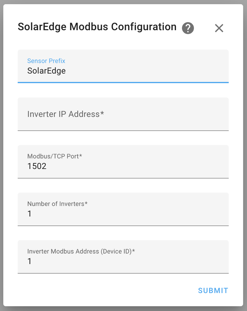
Enter the IP address or host name of your inverter with Modbus/TCP enabled. The default port number is 1502.
If you only have one inverter, leave "Number of Inverters" set to the default of 1. Otherwise, set this number to the total number of inverters in your Leader/Follower chain.
You can configure the Leader (Master) inverter address with the "Inverter Modbus Address (Device ID)" option when setting up the integration. This will be the starting Device ID if "Number of Inverters" is greater than 1. For example, if you configure the Device ID to 4 and Number of Inverters to 3, then your inverters will be addressed as IDs 4, 5, 6. The default is 1, which will address the inverters as 2, 3, 4, etc.
Meters will be automatically detected by default. If you want to enable battery auto-detection, configure the integration after adding it (see Integration Configuration Options).
After setting up the integration, you can configure it by clicking on the "configure" button on your integrations panel:

Default 300 seconds (5 minutes). This option changes how often the inverters are polled for updates.
This option changes the presentation of static device information. Default is enabled.
Select this option to use the _device entity for device information. They will be attributes of the entity.
Disable this option to create individual sensor entities for device information.
Automatically look for and add meter devices on start up. Default is enabled.
Automatically look for and add battery devices on start up. Default is disabled.
Battery registers are not officially supported by SolarEdge. Use at your own risk!
